All About Voltage Ragulators- LM 78xx, LM 317 & through transistors-Opamps
 |
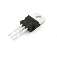
| LM7805 IC, Voltage Regulator |
The purpose of a voltage regulator is to keep the voltage in a circuit
relatively close to a desired value. They are one of the
most common electronic components, the are used since a power supply can produce high current that can damage one component/or whole of the circuit. Voltage regulators have variety of functions. It all depend on the application. Voltage can be changed by varing the
source voltage or Varyng the input impedance of the regulator being used.
| A 7805 Voltage Regulator IC, With its Pin Out Configuraton |
Voltage Regulation Can Be Done Through:
** Through Zener Diodes
** Using ICs available in the market like 7805, 7812 or simply 78xx family of ICs
** By Using a Feedback Mechanism(particularly Negative)
Types of Voltage Regulators:
**Series Pass Voltage Regulator
**Shunt Voltage Regulator
**Step Down Series Switch Regulator
**Step-Up Shunt Switching Regulator
Transistor regulator:(Source Wikipedia)
| Circuit For A Transistor regulator |
In the simplest case an emitter follower is used, the base of the regulating transistor is directly connected to the voltage reference. The stabilizer uses the power source, having voltage Uin that may vary over time. It delivers the relatively constant voltage Uout. The output load RL can also vary over time. For such a device to work properly, the input voltage must be larger than the output voltage and Voltage drop must not exceed the limits of the transistor used.The output voltage of the stabilizer is equal to UZ - UBE where UBE is about 0.7 V and depends on the load current. If the output voltage drops below that limit, this increases the voltage difference between the base and emitter (Ube), opening the transistor and delivering more current. Delivering more current through the same output resistor RL increases the voltage again. When the output voltage increases, due to the reduced base-emitter voltage the BJT will conduct less and the regulation will be maintained. Rv value limits the maximum output current Iout, therefor has a upper limits. Rv (as a rough estimate) should not be larger than (UIn - Uz) / IB, where IB is maximum Iout divides transistor's current amplification ratio.
Regulator Using an operational amplifier(OP-AMP):(Source Wikipedia)
| Regulator Using an operational amplifier(OP-AMP) |
Working: Operational amplifier drives the transistor with more current if the voltage at its inverting input drops below the output of the voltage reference at the non-inverting input. Using the voltage divider (R1, R2 and R3) allows choice of the arbitrary output voltage between Uz and Uin.
Make You OwnVoltage Regulator Using LM 78xx IC:
| Pin Configuration Of 7808 Voltage Regulator |
**LM78xx IC
**Two capacitors (between 100 and 1000 mf)
**Breadboard
**Connecting Wires
# Hold the 7805 voltage regulator so that the printed face is facing towards us. The pin on left is the input pin, where we are going to give input voltage from a source. The middle pin is the ground. The pin on right is our output pin.
# Connect the ground from middle pin of the 7805 with a connecting wire.
# Connect the positive wire from the transformer or the battery to the input of the 7805(left most pin).
# The positive terminal of the capacitor( for electrolytic capacitor ), connect it with the input lead of the 7805.
# Connect the 2nd capacitor between the output and ground pins of 7805. The (-) pin of the capacitor should go with the GND of the 7805 and the (+) with input pin of the 7805.
Your Voltage Regulator is ready!! For Changing the output value we just have to change the capacitor values.
| 7805 Voltage Regulation Circuit |
| Another Implementation Of Previous Voltage regulator Circuit |
** The above circuit shows, that the net value of capacitance can be changes just by adding the capacitors in parallel to already connected capacitors.
| LM317 In a voltage Regulator Circuit |
| Voltage Regulator Circuit |
| Another Circuit For LM 317 Voltage Regulator |
 |
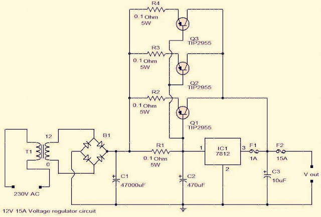
| Circuit For Building A Voltage Regulator Using IC LM 7812, 12V-15A Voltage Regulator Circuit |
 |
| Circuit for building a Voltage Regulator AC 230 V, to 12V 10A By IC LM 7232 |
 |
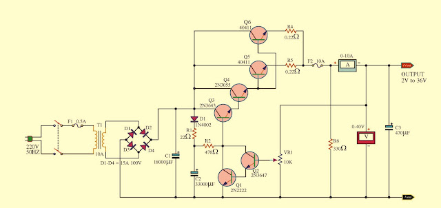
| AC Mains supply to 2 to 36 V Voltage Circuit Using Transistors. |
NOTE:
As they are based on a linear regulator design, the input current required is always the same as the output current. As the input voltage must always be higher than the output voltage, this means that the total power (voltage multiplied by current) going into the 78xx will be more than the output power provided. The extra input power is dissipated as heat. This means both that for some applications an adequate heatsink must be provided, and also that a (often substantial) portion of the input power is wasted during the process, rendering them less efficient than some other types of power supplies. When the input voltage is significantly higher than the regulated output voltage (for example, powering a 7805 using a 24 volt power source), this inefficiency can be a significant issue.
