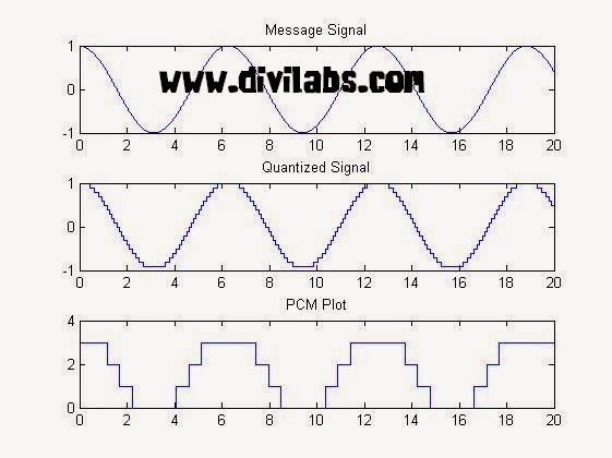
Pulse Code Modulation (PCM) Using MATLAB
PCM is a type of source coding.
Invented by Alec Reeves, it is the standard form of digital audio, CDs, telephony & other digital audio applications. A PCM stream is a digital representation of an analog signal, in which
the magnitude of the analogue signal is sampled regularly at uniform
intervals, with each sample being quantized to the nearest value within a
range of digital steps.
A PCM stream has two basic properties that determine the stream's fidelity to the original analog signal: the sampling rate, which is the number of times per second that samples are taken; and the bit depth, which determines the number of possible digital values that can be used to represent each sample.
 |
| PCM Modulated Sine Wave (Courtesy : Wikipedia) |
In the diagram above, a sine wave
(red curve) is sampled and quantized for PCM. The sine wave is sampled
at regular intervals, shown as vertical lines. For each sample, one of
the available values (on the y-axis) is chosen by some algorithm. This
produces a fully discrete representation of the input signal (blue
points) that can be easily encoded as digital data for storage or
manipulation. For the sine wave example at right, we can verify that the
quantized values at the sampling moments are 8, 9, 11, 13, 14, 15, 15,
15, 14, etc. Encoding these values as binary numbers would result in the following set of nibbles: 1000 (23×1+22×0+21×0+20×0=8+0+0+0=8),
1001, 1011, 1101, 1110, 1111, 1111, 1111, 1110, etc. These digital
values could then be further processed or analyzed by a digital signal processor.
MATLAB Implementation (Simulation) Of Pulse Code Modulation (PCM)
clc
close all
clear all
t = 0:0.0001:20; %sampling at niquist rate
c=input('Enter Bit Depth Of PCM Coding:');
part = -1:0.1:1;%A quantization partition defines several contiguous, nonoverlapping ranges
%of values within the set of real numbers.
codebook = -1:0.1:1.1;%A codebook tells the quantizer which common value to assign to inputs that
%fall into each range of the partition.
msg = cos(t);
[~,quants] = quantiz(msg,part,codebook);%returns a vector that tells which interval each input is in
subplot(3,1,1);
plot(t,msg);
title('Message Signal');
subplot(3,1,2);
plot(t,quants);
title('Quantized Signal');
y = uencode(quants,c);
ybin=dec2bin(y,c); %converting it to final binary form to make it transmit ready
subplot(3,1,3);
plot(t,y);
title('PCM PLOT');
Some Concepts Improtant for Coding Implementation:
Two parameters that determine
a quantization: a partition and
a codebook.
A quantization partition defines several contiguous, nonoverlapping
ranges of values within the set of real numbers.
For example, if the partition separates the real number line
into the four sets- {x: x ≤ 0}
- {x: 0< x ≤ 1}
- {x: 1 < x ≤ 3}
- {x: 3 < x}
partition = [0,1,3];
A codebook tells the quantizer which common value to assign to inputs that fall into each range of the partition. Represent a codebook as a vector whose length is the same as the number of partition intervals. For example, the vector
codebook = [-1, 0.5, 2, 3]; is one possible codebook for the partition [0,1,3].
NOTE: The output PCM Plot & value projection greatly depends on the bit depth you have chosen. More the bit depth used, more closely it will resemble the message signal while plotting the curve.
Sample Input & Output:
Enter Bit Depth Of PCM Coding:2
 |
| PCM (Pulse Code Modulation) in MATLAB 2 bit Coding |
Enter Bit Depth Of PCM Coding:8
 |
| PCM (Pulse Code Modulation) in MATLAB 8 bit Coding |
Hence its also clear by seeing above two implementation that more the bit depth more accurately the message signal are coded. But the drawback of increasing the bit depth is, more number of bits is now to be transmitted.

did it work in scilab 6.0.0 ?
ReplyDeleteU need to check that!
DeleteUencode error need to check it.
ReplyDeleteerror is coming for quants
ReplyDelete