3 options To Remove Country Restriction on watching Youtube Videos

Hello readers today we will see how to remove country restriction from YouTube videos. You might have got some Country Restriction error on some videos of Youtube.com. That is sometime really annoying, when you are looking for a video to get some more idea about that topic you might be needing for your project.
There are many solution for this, you can choose any of the available option, as per your convenience :-
1. Either use VPN to avoid this situation.
2. Or use TOR Browser. Download it from here, http://www.torproject.org.in/download/download-easy.html.en [  this is the best available option ]
3.  Use online proxy sites available online, to use them you need to open them, & just paste the link over the address bar provided by them (in their page, not the browser), and you will able to browse your desired video.
Some of the online proxy sites are, http://www.proxfree.comhttps://arssl.com/youtube-proxy-site,
https://www.4everproxy.com/, etc

You might get some option to select IP Location and Server Location of the proxy you want to view your video. For example your video, is only available in Germany, then always select the option of IP/Server location for Germany.

Hope one of the above methods will solve your problem.

Posted in Digital iVision Labs, Web Apps & Tricks Section. www.divilabs.com

How DOS Prompt & MATLAB Command Window Are The Same?

Yes there are many Similarities between, DOS command prompt ( that you can still access by typing "cmd", in the run window of Windows OS ) & MATLAB's command window working. Thats sometimes give a feeling, that a lot of things in MATLAB,  inspired from this good old operating system. Lets see how..!

Clear Window Command --> clc
This command when given, in matlab, it clears the current command window. Its similar to "cls" [clear screen] command of DOS Prompt.

Print Work Directory --> pwd
This command prints the current working directory in matlab. It takes no input as the argument. But echoes a string in output, that represent the current working directory. This command is similar to "cd", command of DOS Prompt, which when typed without any preceeding word will echo the current directory.

Directroy List Command --> dir
This command in MATLAB has 2 forms, functional form &  command form.
dir('name_of_directory') %Functional form
dir name_of_directory %Command Form

In either of the above mode MATLAB will list all the names of files & directory under the directory named 'name_of_directory'. [ but it should be an existing one, other wise it will echo an error ]

dir command in MATLAB, just like the DOS Prompt counterpart supports the wildcards, for example the command, dir E:\xyz\*.m, will list all the files in the directory in E:\\xyz\\ having the file extension of .m.
But when we use dir as function it returns not a string, but a structure, e.g., dir('E:\xyz\*.m'), now it will return a nX1 structure, where n is the number of .m files in that directory. So we can process the above collected data is different way.

The above command of MATLAB Command window is very similar to DOS prompt, command DIR. Through which we can get the same result [Except the result when we use the functional form in MATLAB].

Make Directory Command --> mkdir
Just like dir command, this command in MATLAB has 2 forms, functional form &  command form.
mkdir('name_of_directory') %Functional form
mkdir name_of_directory %Command Form
Suppose the name of directory we have choosen is "d1", so we have to type as "mkdir d1".
Yes just like DOS, we can also make multiple directory in a single command, just my typing "mkdir d1, d2". When using in it in functional form we should type as mkdir('d1','d2'). The functional form returns the value of 1 if the directory creation is successfully done, 2 if the required directory is already in existance & 0 is unsuccessful in making it, so this thing can be put into a proper use, when it required. The directory name can be relative or a complete address may be provided to create it.

Change Work Directory COmmand -->cd
It hace 2 forms, functional & command form.
cd dir_path or cd('dir_path')

Above is similar to CD command of DOS Prompt.

"cd ..", will be command, to change the current working directory to a higher one. Just like that of "CD..", command of DIS prompt.

NOTE :- "cd" without any input params, is equivalent to "pwd" command.

Copy File Command -->copyfile
Simply type, copyfile('source','destination'), to use it.
Here Source can be a full path addressing the, directory path, file name & file extension, same thing for the 'destination'. Yes the source & destination can be different, in path.
This command is similar to COPY command of DOS Prompt.

Delete File Command --> delete

Type as , delete filename or delete('filename'), the 'filename' can be a file in the current working directory, or a full path specified to the file to be deleted. We can also use wildcards in this command as, "delete *.m", this command will delete all the ".m", files from the current working directory.

Print current Date command --> date
Type "date" in the MATLAB command window and it will return today's date. Just like the "DATE" command in the DOS Prompt.

Closing MatLAB command -->quit

Just type "quit" in MATLAB's Command prompt, and the MATLAB will close, it is similat to "EXIT" command of DOS Prompt.


NOTE:- DOS is not case sensitive, but MATLAB is!

Gears & Their Common Types Used In Robotics

According to Wikipedia definition, a "gear" or "cogwheel" is a rotating machine part having cut teeth, or cogs, which mesh with another toothed part in order to transmit torque, in most cases with teeth on the one gear of identical shape, and often also with that shape (or at least width) on the other gear.
Gears are essentially levers that work using rotational motion. The radii of the different gears indicate that if the effort required will be greater or less than the load. Particularly these type of gears are utilized in robotics, because of there easy implementation:

Spur Gears

Spur gears transfer rotational motion in the same plane. Spur gears or straight-cut gears are the simplest type of gear. These gears can be meshed together correctly only if they are fitted to parallel shafts.
Spur Gear Pair Used In Robotics


Hellical Gears

Hellical gears also transfer rotational motion in the same plane ( similar to spur gear)however, the gear teeth are designed to make the motion transfer much smoother than them. Helical gears can be meshed in parallel or crossed orientations. For example the below one.
Helical Gear Used In Robotics

Bevel Gears

Bevel gears help in changing the direction of the rotational motion. An example is shown in Figure . The shafts in bevel gears do not have to be at right angles. They can be at any other angle such as 45 degrees. The angle between the shafts can be anything except zero or 180 degrees.
Bevel Gear
Bevel Gear

 Worm Gears

Worm gears also change the direction of the rotational motion. Worm gear produces motion at right angle to the input gear. A worm gear is usually meshed with a spur gear or a helical gear, which is called the gear, wheel, or worm wheel.

Worm Gear ( Courtsey: Wikimedia)


Rack and Pinion Gears

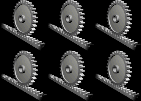
Rack and pinion gears convert rotational motion into translational or vice versa. A rack is a toothed bar or rod that can be thought of as a sector gear with an infinitely large radius of curvature. An example is shown .
Rack & Pinion Gear ( Courtsey: Wikimedia)

 Planetary Gears

Planetary gears provide more complex control over rotational motion. An example is shown in Figure. It has a central gear (sun gear), planet gears, ring gear, and an arm. The input and output shafts can be connected to the ring gear, the sun gear or the arm, giving different angular speeds. One can have different number of planet gears including one.
http://steverose.com/Articles/Planetary_Gears.gif

 Compound Gears

Gears can be connected to each other to produce very large mechanical ad-vantages. These are called compound gears. An example is shown .

Compound Gear
Compound Gear

Arduino Communicating with Another Arduino

Yes it is possible to make 2 Arduinos to get talking with each other. Having Arduino-Arduino communication can be useful for many projects, such as having one Arduino for displaying a detailed output in a GLCD and another sensing the surroundins and then relaying the inputs to the other. This can be done in several methods, using I2C and Serial.
This article will focus on Arduino to Arduino communication through the serial ports (RX and TX or pin 1 & 0 of Arduino UNO particularly, and if its MEGA, you can connect it to any of the pair of RX & TX pins).

The data is sent through serial communication ports in binary form, that is in bytes. Arduino reads Bytes by Bytes sent by the other. Even the characters sent through the serial port of Arduino, first it is converted to data bytes then transmitted & then decoded as a character.

To get an idea about it, there are several example codes available for the serial communication using arduino, just go to "File >> Examples >> Communication" in the Arduino IDE.

One of the code to upload on the Arduino for Serial Communication is:
 
void setup()  
{
  Serial.begin(4800);
}

void loop() {
  Serial.print('1');
  delay(500);
  Serial.print('0');
  delay(500);
}
The above code will initialize the serial communication port with a BAUD rate of 4800bps. And in one second it will send a character value of '1' in one half of the second & in the other half it will send '0'. That is the wave generated by it will have the frequency of 1Hz.

Sender Code

The sender code changes characters into byte stream &, if necessary, it changes number values into characters before turning it into bytes. Below is a sample of the Sender code:
char xyz[3];
void setup()  
{
  Serial.begin(4800); //baud rate define
}

void loop()  
{
  int value=888; //Or a sensor output from an Input Analog Pin 
  itoa(value, str, 10); //Turn any value into a character array
  Serial.write(str, 3); //to send the character through the serial port
}
 
Arduino to Arduino Connection For Serial Communication ( Schematic Created Through Fritzing Software )
 

Receiver Code

The receiver will then receive the byte array & decode it. Below is the code to be uploaded in the receiver Arduino board. The receiver Arduino will receive the serial data, and then print to the Serial Monitor so that the user can view it
char xyz[3];
void setup()  
{
  Serial.begin(4800);
  Serial1.begin(4800); // this notation is for arduino MEGA only
}

void loop()  
{
  int i=0;

  if (Serial1.available())  
{
    delay(100); 
    while(Serial1.available() && i<3)  
{
      str[i++] = Serial1.read(); //read the string of length 4
}
    str[i++]='\0';
}

  if(i>0)  
{
    Serial.println(str,3);
  }
}
 
Thus 2nd arduino, will display on the serial monitor 
whatever the the 1st arduino will send.
 
The above Experiment can be also done effectively through I2C pins.

NOTE:- The BAUD rate or Serial Communication rate should be equal in order to make them communicate successfully.


One of the reader commented: <Tore Eriksson>
If I want just one-way communication from one Arduino to another can I exclude the other wire or is there still some handshaking that requires wires both ways? The answer is you need just one wire (plus Ground, of course!) if you want just one-way communication.

If anyone wishes to make a very stripped down example with no confusing extra information, I would have liked to see a one-way communication example with only one signal wire.

In my experiment, I had a switch on one pin of the sending Arduino. Depending on how long time I pressed that switch, the pin 13 LED flashed a number of times. After releasing the button, the first Arduino sent a message to the second Arduino, telling the number of flashes, and then the second Arduino repeated the flash sequence on its pin 13 LED.

Comparing NI LABVIEW & C Programming language

Here is one of the most remarkable article that we have came across, while browsing across the NI LABVIEW Knowledge Base Community, decibel.ni.com. While browsing through various article on the question of comparing NI LABVIEW graphical programming & the conventional programming using the languages like C, C++, JAVA etc.
So we decided to present that article in unedited form, to preserve its beauty, and giving all the credits to the original author with all the links which were there in the article. [ If still someone not willing to see this article here, just contact us, we will delete this article ASAP ]

So it goes like this......

Why is LabVIEW better than C?” As a LabVIEW Product Manager, I get asked this question a lot.
Honestly, it is the wrong question to ask. It becomes a valid question with a little nuance and application context (for example, “Which is better for this task, under these constraints?”). Without this detail, it’s like asking why bread is better than flour. 


If you want to build a measurement or control system, then NI LabVIEW system design software is a tool that can save you the risk, expense, and inconvenience of building your own from low-level languages like C. I’m not suggesting that LabVIEW is a “better” programming language than C—especially considering that large portions of LabVIEW are written not only in G but also in C and C++. Rather, they have different strengths that programmers should understand to succeed.
Capture.JPG
How is LabVIEW like bread? Read on.

The relationship between LabVIEW and C is similar to bread and flour. If you want to make a sandwich, start with bread. If you want to bake a cake, start with flour. Baking bread with flour from scratch can be expensive and time consuming (especially if you just want a quick snack), but when it comes to a cake, flour is essential. Similarly, you might find it challenging to decide which programming language is best for your task. It comes down to using the right tool for the right job.
C Gives You Low-Level Control
C is often better for applications with tight resources that must be closely managed. Since C is a relatively low-level language, it forces you to consider and specify even the smallest details, such as memory assignments and threads. A good programmer can use this low-level of control to eliminate the overhead in most higher level implementations. At this level, you can also take advantage of target architecture or host operating system properties to achieve greater performance.

NI programmers wrote most of the LabVIEW libraries in C or C++ for this reason. Operations like file I/O and analysis are as fast in LabVIEW as they are in C because they are written in low-level languages and optimized for each of the platforms and operating systems that LabVIEW supports.
Efficiency Versus Control
At some point, developer efficiency trumps the need for hand-optimized code. Relinquishing a little control to stand on the shoulders of those who have solved similar problems can benefit many projects in terms of quality productivity. Programming languages are constantly progressing toward higher levels of abstraction. This helps you focus on the problem at hand instead of the minutia of the computing.
          

LabVIEW: For Parallel Execution and Real-World I/O
No matter what the implementation language, high-level system design and low-level implementation must inevitably split.
In measurement and control applications, programming is just one task of a system designer. Engineers often don’t have time to keep up with or rewrite old software to support the advancements in computing and measurement hardware, operating systems, and so on. They add value by figuring out how to acquire, manipulate, and present real-world data—not by coming up with new ways to handle memory allocations and thread pools. By using LabVIEW,  you can  build on top of tested, supported, and maintained libraries of lower level code from NI. Choosing C means you’ll need to implement, support, and maintain your own lower level libraries or purchase them from a vendor (NI offers NI LabWindows /CVI software and NI Measurement Studio for this use case).
Syntax-wise, C is optimized for sequential execution of instructions as fast as the CPU can handle them. This is perfect for pure computation, when only one task is being executed and instructions are more basic. The graphical syntax in LabVIEW, on the other hand, is optimized for the parallel execution of tasks that have real-world timing constraints. 
LabVIEW is more than just a programming language and associated libraries. When you use the LabVIEW integrated development environment (IDE) with 3rd party NI hardware, you get a development experience that is greater than the sum of its parts. The software is aware of available hardware resources and can present available I/O channels and execution targets as drop-down menus and project items. You can prevent or catch incorrect configurations during editing, to avoid costly, hard-to-debug  runtime errors. Next-generation measurement hardware (such as the NI PXIe-5644R vector signal transceiver) even allows LabVIEW to redefine the firmware of the hardware to reach performance levels that traditional, distinct programming languages and instruments can’t.

Too many projects end up late or over budget because people underestimate the efforts required to stitch together parts from disparate sources. When you use LabVIEW, your hardware drivers return data in the same format as the analysis libraries consume, your UI widgets display technical data in the same format that the analysis libraries produce, eliminating the need to piece together components. 
So Which is Better: LabVIEW, or C?           
The answer might as well be “42.” To draw from The Hitchhiker’s Guide to the Galaxy, the answer isn't meaningful until you know which question you are asking or what problem you are trying to solve. LabVIEW and C are both useful tools that, in the hands of skilled users, can solve almost any problem: LabVIEW tends to be better for high-level test, measurement, and control applications, and C is more apt for lower level implementations of computationally intensive tasks.
The next time someone asks you whether LabVIEW trumps C, feel free to answer “42”. It may be the only response that will get the discussion heading in the right direction.
To learn more about LabVIEW and the NI integrated development environment, visit ni.com/labview.

by  JoelleP

Hope you enjoyed reading this as we did.

Mapping the sensor output to another set of values through Arduino Programming-map() function

Directly jumping on the piece of code/sketch:

// set the mappedSensorValue to the value of the map() function
int mappedvalue = map(sensoroutputvalue, 0, 1023, 0, 9);

Here the variable "mappedvalue" will store the mapped value or range conserved value which is a modified form of the sensor value that is got feeded in the Arduino.

When ever a sensor return a particular reading, which is actually in the form of voltage, the ADC of Arduino converts or dissects the value in 1024 values, i.e., the lowest value is being assigned to 0 & the highest[particularly +5 volts or the voltage value at ARef pin] be 1023.

But why are we gonna need that much of value variations. Some time even scale of 1 to 10 is enough.[actully more than enough in case of just a estimated result]. So by map() function of Arduino Programming Language.

The map [map()] function as you are able to see in the above example, has actually 5 arguments!
1st, is the "sensoroutputvalue", as the name is suggesting, it the value that sensor gives to the Arduino.
2nd is the "0", which is actually the lowest value that Arduino ADC can give.
3rd is the "1023", which is actually the highest value that Arduino ADC can give.
4th is again a "0", well that actually depends on the user choice/need. If we want a range of 6 to 9 we will set this arguement as just "6".
5th is "9", which is actually the highest value of the user defined range of mapping.

So after executing this function the mapped value will be stored in the variable named "mappedvalue".

the ranges 0 through 9 based upon the pattern we’ve just described will be like

0 To 102 -->0
103 To 205 -->1
206 To 308 -->2
309 To 411 -->3
412 To 514 -->4
515 To 617 -->5
618 To 720 -->6
721 To 823 -->7
824 To 926 -->8
927 To 1023 -->9

here "-->" denotes the mapping, & the range of values to the left is the range of sensor output, as interpretted by ADC & the right value will be the mapped value of that range.

Map function [map()] is just doing a simple arithmetic calculation, for mapping out the values.

It is like:-
[sensoroutputvalue/1024]*9, here 9 is the max limit of the required mapped value.

Getting Hyperterminal On Work For Windows 7 & Windows 8

The good old Hyperterminal which is a Windows program used for Communication of text or binary data via Serial communication [COM] ports or TCP/IP protocols. Unfortunately on Windows 7 or even Windows 8 it is not provided, as it was in Windows XP & later version.
Many a times embedded system engineers need this program for sending information through Serial COM port, to the microcontrollers they are using [8051, AVR etc] & other devices they want to control through it. For many of them it will never be a wiser solution to downgrade the Operating System just for getting this program.

Simplest Solution is:
-->Log ON to a computer that is still using the operating system of Windows XP.
-->Copy the two  files associated with hyper terminal,they are hypertrm.exe and hypertrm.dll.
NOTE:- Copying these two file together is necessary as they depend on each other, i.e., they will not work single.
The above two file will be found in the Windows XP directories,
C:\\Program Files\\Windows NT\\hypertrm.exe
C:\\WINDOWS\\system32\\hypertrm.dll
Put these file in a Folder anywhere in your windows 7 or 8 system, and double click or press enter key to execue hyperterm.exe to start Hyperterminal in your Windows 7 or 8 system..!

Second solution is to download it [not so difficult indeed]:

You can download the files in a zip-package from here:

**Courtesy  KMTRONIC**

Hyperterminal in Windows RAR
Hyperterminal In Windows 7
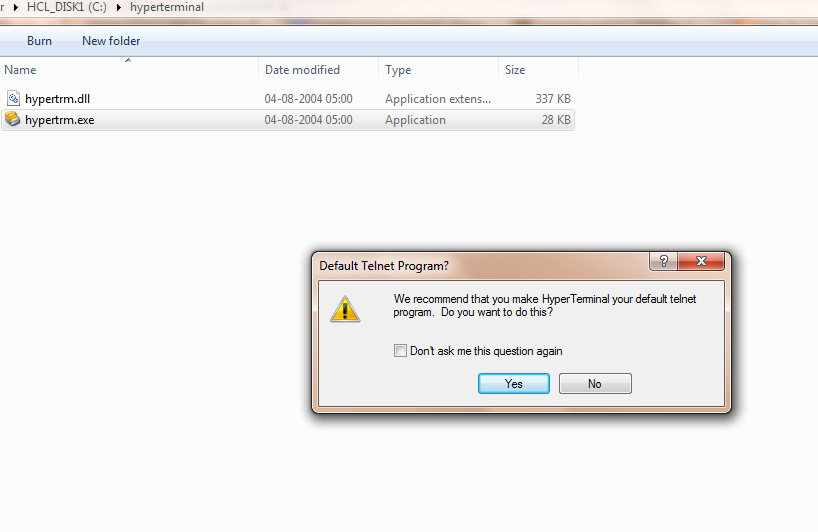
After clicking on hyperterm.exe it will ask you to make it as a default Telnet Program, You will have to click Yes or No as per your need of it. If you don't use any other Telnet Client, no harm in Clicking Yes, but to be on safe side[ if don't wanna disturb settings of your computer ], click No, and put a tick mark on the option to don't ask you again.

Hyperterminal Dialog Box asking the permission of making it as a default telnet program
Giving the connection name & selecting some icon
Then after that dialog box the Hyperterminal will open, with another question. It will ask you to give the connection name & selecting the icon [which will be invisible though, if you are using windows 7 or 8].
Click "Ok" After doing this.

Dialing A Telephone From Hyperterminal
After clicking "OK", in the previous step, Hyperterminal will ask you to dial a Telephone Number, If you want just enter it and click "OK", of not click on "Cancel".

Working With Hyperterminal:-

If you wanna select a COM port, a simple procedure if that:-
Click on "File", Then on "Properties", as sown in the snapshot.
Setting up a COM port in Hyperterminal
Various options of connecting in Hyperterminal
Once you have clicked in the "Properties", option you will see like this. Go to "Connect Using" drop down list, and select the COM port desired or TCP/IP or the Modem through which you wanna communicate.

Call Menu in Hyperterminal

Clicking Call menu you will see 2 live options, Call & Wait For Call and two dead option [ which will come alive when you are in between a call ]. Clicking on Call will open the same dialog option, which was initially opened, asking the telephone number.

Transfer Menu In Hyperterminal
It is visible that it has 5 options, that is to Send File, Receive file [Both for Binary or Text file], Capture text,  Send Text File & Capture to Printer.

The Send File Option:
Sending File With Hyperterminal
Browse your file that you want to send, and select the desired protocol, which will be used to send the file. Both sending and Receiving device must agree with the protocol type to use.

Receiving File In Hyperterminal
Browse the desired folder you want to put your received file to, and select the reveiving protocol.

Capturing Text In Hyperterminal
Yes it is possible to Capture the text whatever is received in the current session to a Text File.
Just click on the Capture Text option from the Transfer Menu, and browse the pre-created TXT file. Best way to do is, place a empty TXT file.

Sending Text File Through Hyperterminal
Just Click on the Option Send Text File, And you will se another dialog box saying to browse for the text file. Browse it, and click on Open. Hyperterminal will now make an automatic arrangement to send it through the COM port pre specified.


Procedure of Creating .hex file in KEIL uVISION 4, for 8051 Microcontroller

Firstly your Computer system must have Keil uVISION 4, installed! The following steps are also very much applicable to Keil uVISION 3 [A later version of it].
If you haven't installed it yet, go and download it from the following link http://keil.com/downloads. There you can select the various options available, such as code limited version, trial will full lenght codes, etc. So go to the program location & double click on the Uv4.exe, that is the main executable of it. Or if you are a windows 7 user, them simply go on start menu, them search as "keil" without quotes, if you have installed it correctly, then you will find this on the top of results.
Kiel as seen in Windows 7 program search

Once it is opened,  your workspace will something like this.


Keil uVision 4 Workspace Startup look
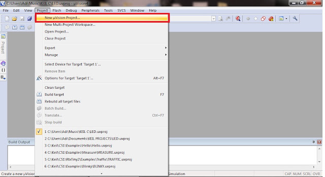
Now you have to create the Keil uVision project in order to proceed further. For that Click on "Project" & select "New uVision Project".


Keil uVision 4 Project Menu Option

Give a name to your project, the project name can be anything but, should not be starting with a digit.


Project Save Option in Keil uVision 4
Once named the project. Click on "Save".
Now a new window will open, which will tell you to select the device, so it will depend on your vendor, like nxp, atmel, intel, who manufacture the 8051 IC, & you have purchased one of them. Select the exact configuration to get go, on the next step. To find the exact version of 8051 IC you are having, look deeply on your 8051 IC. Then match exact codes for vendors & version. Here the vendor is Atmel & device is AT89C51.
After selecting your device click on "OK"


Selecting a Vendor & Version/Type of 8051 IC, From the list proided
Now, one dialog box will appear stating,  to copy 'STARTUP.A51' to project folder & add file to Project, Select Yes.

Dialog Box in Keil, to copy STATUP.A51 to project folder & add the file to the project


Now after creating the project you need to create the source, which Keil will later on Compile(on your command). For that go to the "File" menu, and select "New".
Creating New File in Keil uVision 4
  A text window will open, where you are going to write a code to compile & create the .hex file. Write down your code  & save. For Assembly language file please save the file with ".asm" extension, if instead writing a code in C save it with a ".c" extension.
Writing the source code to be compiled in KEIL uVISION 4


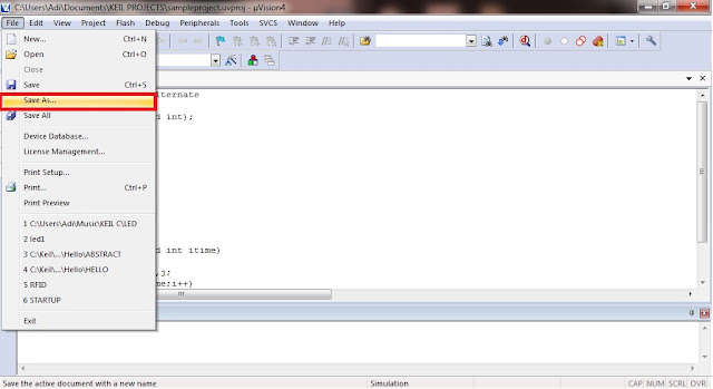
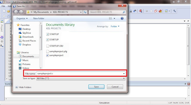
After Finishing the code, save the file, for that go to the File menu and click on Save or Save As. As this is the file creation step both will result in the same.
Saving a file in KEIL uVISION 4
Save the file as any name, you want, but don't forget to give the file an extension .asm or .c, depending on what you are writing.
saving a file in KEIL uVISION 4
Saving a file in KEIL uVISION 4
Ne just to compile the code,  by selecting,  "Build the Target" option from "Project" menu. But before that, we need to go to the Project menu and select Options for Target 'Target 1'

Keil uVISION 4 Project Option
A dialog box will open. Select the Output menu & put a tick on Create HEX file option.
NOTE: If you havn't selected this option you will not be able to create .hex file to burn it into the 8051 development board.

Selecting Create HEX File Option

Now click on the "Project" Menu, & select "Build Target".

Building Target or Compiling code in KEIL uVISION 4

After A successful build your HEX file will be created & can be found in the project folder, where your source file is. It will be with the extension .hex & with the same name as the Project.
Browse it through, & with software like "flash burner", load it to the Micro-controller 8051, to work as desired.

VIDEO PROCESSING Using MATLAB

MATLAB provides the necessary functionality for basic video processing tasks using a limited number of video formats. Not very long ago, the only video formats supported by built-in MATLAB functions was only the AVI, through functions such as aviread, avifile, movie2avi, & aviinfo. Moreover, the support was OS dependent & limited only to a few video codecs. Then with newer versions of MATLAB, new library functions like mmreader, was introduced to extend video support of video formats such as AVI, MPEG, and WMV (But it was true for only Windows Platform).
MATLAB represent the monochrome & colored video by creating the manipulative, 3 dimensional or 4 dimensional matrix, but provided that the video sequences are short, i.e., only few minutes of it.
When a frame needs to be processed individually, it can be easily converted into an image using the "frame2im" function, which can then be processed using any of the functions available in the Image Processing Toolbox of MATLAB.

The MATLAB functions associated with reading video files:
aviread: to read an AVI video file & store the frames into a MATLAB video structure, which may me actually 3D or 4D matrices, containing information about the monochrome or colored frames.
aviinfo: returns a structure who contains information such as, frame width, frame height, total number of frames, frame rate, file size, etc
mmreader: constructs a multimedia [here mm stands for multimedia] object that can read video data from a variety of multimedia file formats.

Processing Video Files In MATLAB
Steps can be put in a loop if the same type of processing is to be applied to all frames of video file:
1. Convert frame to an image using frame2im.
2. Process the image using any function as required by the image processing task.
3. Then Convert the result back into a frame using im2frame function.

Playing Video Files In MATLAB
movie: a built-in video player of MATLAB
implay: a fully functional built in image & video player with many options.

Writing Video Files in MATLAB
avifile: creates a new AVI file that can then be populated with video frames
in a variety of ways.
movie2avi: creates an AVI file, from MATLAB Frame Sequence.

An Arduino Sketch That will Make your LED Blink & Much More than That!

I think you know that a source code or program in Arduino Programming Language, is known as sketch. Told to you so you dont get confused. LED blinking program is considered to be the Hello World Program for various Microcontrollers, and for Arduino here it is!

/*
Blinking an LED, by turning on an LED on for half a second, then off for another half of the second, continuously forever.
This example code is in the public domain.
*/


// Pin 13 has an LED connected on most Arduino boards.
// give it a name:
int led=13;
// the setup routine runs once when you press reset:
void setup() {
// initializing the digital pin as an output.
pinMode(led, OUTPUT);
}
// the loop routine runs over and over again forever:
void loop() {
digitalWrite(led, HIGH); // turn the LED on (HIGH is the voltage level)
delay(500); // wait for 500 milliseconds, or half a second
digitalWrite(led, LOW); // turn the LED off by making the voltage LOW
delay(500); // wait for 500 milliseconds, or half a second
}
//End of the program

LED Blinking With Arduino
LED Blinking With Arduino ( A simple connection indeed, just insert the LED like that!), but applicable to 1 LED only

NOTE: One caution to be expressed that, you should consider it (one of the terminal of the LED ) connecting with a resistor ( 330 ohms or nearby ) to limit the current, to avoid burnout.

The following video will show you how the above code will work.


You can also try these blinking code with 2 or even array of LEDs, if your arduino board has got the pins in lesser number, try the multiplexing & charlieplexing techniques, which will lead you to use more LEDs that actual number of pins on your board.
Suppose You have connected your 2 LEDs in pin 12 & 13 respectively.
So the Arduino Sketch/Program will go like this:-

int led1= 13;
int led2= 12;
// the setup routine runs once when you press reset:
void setup() {
// initializing the digital pin as an output.
pinMode(led1, OUTPUT);
pinMode(led2, OUTPUT);
}
// the loop routine runs over and over again forever:
void loop() {
digitalWrite(led1, HIGH);// turn the LED 1 on (HIGH is the voltage level)
digitalWrite(led2, HIGH);// turn the LED 2 on (HIGH is the voltage level)
delay(500); // wait for 500 milliseconds, or half a second
digitalWrite(led1, LOW); // turn the LED 1 off by making the voltage LOW
digitalWrite(led2, LOW); // turn the LED 2 off by making the voltage LOW
delay(500); // wait for 500 milliseconds, or half a second
}
//End of the program

Simple isnt it. The above program will give you 2 LED's blinking at the same time, you can try some other varient of this code, that will do the following:-

Keeping one LED High the other goes Off, and vice versa with the other.

int led1= 13;
int led2= 12;
// the setup routine runs once when you press reset:
void setup() {
// initializing the digital pin as an output.
pinMode(led1, OUTPUT);
pinMode(led2, OUTPUT);
}
// the loop routine runs over and over again forever:
void loop() {
digitalWrite(led1, HIGH);// turn the LED on (HIGH is the voltage level)
digitalWrite(led2, Low);// turn the LED on (HIGH is the voltage level)
delay(500); // wait for 500 milliseconds, or half a second
digitalWrite(led1, LOW); // turn the LED off by making the voltage LOW
digitalWrite(led2, HIGH); // turn the LED off by making the voltage LOW
delay(500); // wait for 500 milliseconds, or half a second
}
//End of the program

In the above program, the LED 1 which is connected to pin 13, will be glowing bright ( i.e., ON), when the other LED 2 which is connected to pin 12, is OFF & the vice versa is true for the next 500 milliseconds time span.

Now suppose for an another varient of LED blinker, you have now 6 leds connected to digital IO pins, 8,9,10,11,12,13. Now what you want is like the light is running from one end to another. Like it is starting from LED connected to pin 7 & going through all pins in between it ends up in pin 13 connected LED, that will give the illusion of a running light pattern that we will make through arduino.

So here is the code you will proceed.
int led1= 8;
int led2= 9;
int led3= 10;
int led4= 11;
int led5= 12;
int led6= 13;
// the setup routine runs once when you press reset:
void setup() {
// initializing the digital pin as an output.
pinMode(led1, OUTPUT);
pinMode(led2, OUTPUT);
pinMode(led3, OUTPUT);
pinMode(led4, OUTPUT);
pinMode(led5, OUTPUT);
pinMode(led6, OUTPUT);
}
// the loop routine runs over and over again forever:
void loop() {
digitalWrite(led1, HIGH);
delay(200);
digitalWrite(led2, HIGH);
digitalWrite(led1, LOW);
delay(200);
digitalWrite(led3, HIGH);
digitalWrite(led2, LOW);
delay(200);
digitalWrite(led4, HIGH);
digitalWrite(led3, LOW);
delay(200);
digitalWrite(led5, LOW);
digitalWrite(led4, HIGH);
delay(200);
digitalWrite(led6, LOW);
digitalWrite(led7, HIGH);
delay(200);
}
//End of the program

The run if the light will complete in 1.2 seconds, and you can readily turn the speed of it more faster or more slower. The above way of doing it, is actually an inefficient way of doing it. Later on if you got much experienced in its programming you will do it, in a much shorter way, using arrays, or your custom made methods!

Getting back to the 2 LEDs example, that are connected to pins 12, & 13. Suppose we want to transmit an optical code to the other end, which will turn led 1 (which is taken to be green) five times, LED 2 2 times (that is red in color) & then green again 2 times. When this color code is conveyed to the end user that means, something to him! [That you decide, its your secret message!!]
May be you are thinking that it will be a veri long program, like the previous one, but no, it will not be so....
So the code for this would be like.

int i=0;
int led1= 13;//Green one
int led2= 12;/Red one
// the setup routine runs once when you press reset:
void setup() {
// initializing the digital pin as an output.
pinMode(led1, OUTPUT);
pinMode(led2, OUTPUT);
}
// the loop routine runs over and over again forever:
void loop() {
for(i=0;i<5;i++)
{
digitalWrite(led1, HIGH);
delay(100);
digitalWrite(led1, LOW);
delay(100);
}
for(i=0;i<2;i++)
{
digitalWrite(led2, HIGH);
delay(100);
digitalWrite(led2, LOW);
delay(100);
}
for(i=0;i<2;i++)
{
digitalWrite(led1, HIGH);
delay(100);
digitalWrite(led1, LOW);
delay(100);
}
}
//End of the program

So the program will do your someting like cryptographic work even....!!