BER and SER MATLAB Simulation of Non Square (Rectangular) Constellation QAM [8-QAM] in AWGN Channel
QAM (Quadrature Amplitude Modulation) is widely used in physical digital communication systems, such as WiFi enabled devices, etc. Generally, a square constellation of QAM is preferred, that is because these schemes are easy to Modulate and Demodulate. Any QAM constellation can be considered as a combination PAMs, i.e., both square and rectangular QAM can be thought as a combination of PAMs.
According to a study, End-to-End Energy Modeling and Analysis of Long-Haul Coherent Transmission Systems, the error-rate performance of 8-QAM is close to that of 16-QAM (only about 0.5 dB better), but its data rate is only three-quarters that of 16-QAM. These effects can be seen in the code below, by further extending it to compare with other modulation scheme's BER.
The constellation of the 8-QAM (considering gray mapping) in our scheme looks like. Same result of BER/SER will be obtained if the constellation is 90 Degree rotated about the origin (In the code I have done that).
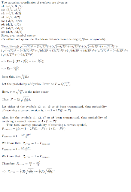
Then I have derived the theoretical SER expression in terms of Q-Functions, which is given below. (Click to expand the derivation)
Now in the MATLAB code (below-bolded) of 8-QAM I have simulated BER and SER curve. Additionally Constellation is also plotted.
clc
clear
close all
nbits=3e7; % No. of bits to be generated
M=8; % for M-ary modulation scheme
nBitsPerSym = log2(M); % Bits per symbol
% For 8-QAM
map=[-1+3j,-1+1j,-1-3j,-1-1j,1+3j,1+1j,1-3j,1-1j]; % Gray Coded Mapping
figure
plot(real(map),imag(map),'r*');
title('Constellation diagram for Transmitted Symbols');
xlabel('Inphase component');
ylabel('Quadrature component');
axis([-3 3 -3 3]);
sym_map =sqrt(1/6)*map;
% Normalizing the constellation with its Avg. Symbol Energy
refI = real(sym_map);
refQ = imag(sym_map);
EsN0dB=0:18; % Es/N0 in dB scale
EbN0dB=EsN0dB-10*log10(nBitsPerSym); % Eb/N0 in dB scale
simulatedBER = zeros(1,length(EbN0dB));
theoreticalBER = zeros(1,length(EbN0dB));
theoreticalSER = zeros(1,length(EbN0dB));
symbErrors = zeros(1,length(EbN0dB));
count=1;
for i=EbN0dB
data_bits=double(rand(1,nbits)>=0.5);
% Generating random bits
inputSymBin=reshape(data_bits,nBitsPerSym,[])';
% Reshaping to form symbol
b = inputSymBin*(2.^((nBitsPerSym-1):-1:0)).';
% Converting bits to symbol
s=sym_map(b+1).';
%M-QAM Constellation mapping through Index Values
EbN0 = 10.^(i/10); %linear scale
EsN0 = 10.^(EsN0dB(count)/10); %linear scale
noiseSigma = sqrt(1./(2*nBitsPerSym*EbN0));
%Sigma for AWGN normalised per bit
n = noiseSigma*(randn(1,length(s))+1i*randn(1,length(s)))';
y = s + n; % AWGN addition to signal vector
demodSymbols = zeros(1,length(y));
for j=1:length(y)
[minVal,minindex]=min(sqrt((real(y(j))-refI(1,:)).^2+...
(imag(y(j))-refQ(1,:)).^2));
%Finding the minimum Eucledian Distance
demodSymbols(j)=minindex-1;
end
symbErrors_t=b.'-demodSymbols;
symbErrors(count)=sum(symbErrors_t(:)~=0)/(nbits/nBitsPerSym);
% Simulation SER Calculation
demodBits=dec2bin(demodSymbols)-'0';
outputSymBin=reshape(demodBits.',1,[])';
% Symbols to bits
bitErrors=sum(sum(xor(outputSymBin.',data_bits)));
simulatedBER(count) = bitErrors/nbits;
% Simulation BER Calculation
theoreticalSER(count)=(5/2)*qfunc(sqrt(EsN0/3))-...
(3/2)*qfunc(sqrt(EsN0/3))*qfunc(sqrt(EsN0/3));
% Theoritical SER
count=count+1; % Index Update
end
figure;
semilogy(EbN0dB,simulatedBER,'r-*');hold on;
title('BER Vs Eb/N0 (dB) for 8-Ary Modulation');
legend('Simulated');
axis('tight');
grid on;
xlabel('Eb/N0 dB');
ylabel('BER - Bit Error Rate');
grid on;
figure;
semilogy(EsN0dB,symbErrors,'k-o');hold on;
semilogy(EsN0dB,theoreticalSER,'r-*');
title('SER Vs Es/N0 (dB) for 8-Ary Modulation');
legend('Simulated','Theoretical');
grid on;
xlabel('Es/N0 dB');
ylabel('SER - Symbol Error Rate');
grid on;
% Code End
The above code furnishes the results as:
Author: Vibhutesh Kumar Singh
According to a study, End-to-End Energy Modeling and Analysis of Long-Haul Coherent Transmission Systems, the error-rate performance of 8-QAM is close to that of 16-QAM (only about 0.5 dB better), but its data rate is only three-quarters that of 16-QAM. These effects can be seen in the code below, by further extending it to compare with other modulation scheme's BER.
The constellation of the 8-QAM (considering gray mapping) in our scheme looks like. Same result of BER/SER will be obtained if the constellation is 90 Degree rotated about the origin (In the code I have done that).
 |
| 8-QAM Constellation with Gray Mapping |
 |
| Derivation is 8-QAM Probability of Symbol Error |
clc
clear
close all
nbits=3e7; % No. of bits to be generated
M=8; % for M-ary modulation scheme
nBitsPerSym = log2(M); % Bits per symbol
% For 8-QAM
map=[-1+3j,-1+1j,-1-3j,-1-1j,1+3j,1+1j,1-3j,1-1j]; % Gray Coded Mapping
figure
plot(real(map),imag(map),'r*');
title('Constellation diagram for Transmitted Symbols');
xlabel('Inphase component');
ylabel('Quadrature component');
axis([-3 3 -3 3]);
sym_map =sqrt(1/6)*map;
% Normalizing the constellation with its Avg. Symbol Energy
refI = real(sym_map);
refQ = imag(sym_map);
EsN0dB=0:18; % Es/N0 in dB scale
EbN0dB=EsN0dB-10*log10(nBitsPerSym); % Eb/N0 in dB scale
simulatedBER = zeros(1,length(EbN0dB));
theoreticalBER = zeros(1,length(EbN0dB));
theoreticalSER = zeros(1,length(EbN0dB));
symbErrors = zeros(1,length(EbN0dB));
count=1;
for i=EbN0dB
data_bits=double(rand(1,nbits)>=0.5);
% Generating random bits
inputSymBin=reshape(data_bits,nBitsPerSym,[])';
% Reshaping to form symbol
b = inputSymBin*(2.^((nBitsPerSym-1):-1:0)).';
% Converting bits to symbol
s=sym_map(b+1).';
%M-QAM Constellation mapping through Index Values
EbN0 = 10.^(i/10); %linear scale
EsN0 = 10.^(EsN0dB(count)/10); %linear scale
noiseSigma = sqrt(1./(2*nBitsPerSym*EbN0));
%Sigma for AWGN normalised per bit
n = noiseSigma*(randn(1,length(s))+1i*randn(1,length(s)))';
y = s + n; % AWGN addition to signal vector
demodSymbols = zeros(1,length(y));
for j=1:length(y)
[minVal,minindex]=min(sqrt((real(y(j))-refI(1,:)).^2+...
(imag(y(j))-refQ(1,:)).^2));
%Finding the minimum Eucledian Distance
demodSymbols(j)=minindex-1;
end
symbErrors_t=b.'-demodSymbols;
symbErrors(count)=sum(symbErrors_t(:)~=0)/(nbits/nBitsPerSym);
% Simulation SER Calculation
demodBits=dec2bin(demodSymbols)-'0';
outputSymBin=reshape(demodBits.',1,[])';
% Symbols to bits
bitErrors=sum(sum(xor(outputSymBin.',data_bits)));
simulatedBER(count) = bitErrors/nbits;
% Simulation BER Calculation
theoreticalSER(count)=(5/2)*qfunc(sqrt(EsN0/3))-...
(3/2)*qfunc(sqrt(EsN0/3))*qfunc(sqrt(EsN0/3));
% Theoritical SER
count=count+1; % Index Update
end
figure;
semilogy(EbN0dB,simulatedBER,'r-*');hold on;
title('BER Vs Eb/N0 (dB) for 8-Ary Modulation');
legend('Simulated');
axis('tight');
grid on;
xlabel('Eb/N0 dB');
ylabel('BER - Bit Error Rate');
grid on;
figure;
semilogy(EsN0dB,symbErrors,'k-o');hold on;
semilogy(EsN0dB,theoreticalSER,'r-*');
title('SER Vs Es/N0 (dB) for 8-Ary Modulation');
legend('Simulated','Theoretical');
grid on;
xlabel('Es/N0 dB');
ylabel('SER - Symbol Error Rate');
grid on;
% Code End
The above code furnishes the results as:
 |
| SER vs Es/N0 for 8-QAM modulation scheme (The theoretical and simulation result matched for AWGN channel) |
 | |
|

1 comments: