Preparing or Creating an effective Imaging Environment for its use in an Image Processing Task
In order to properly prepare your
imaging environment for your specific application, we must first examine our
task completely to determine your machine vision requirements. That is what we exactly require from our Image Processing task to infer.
During system setup, we decide the type of
lighting and lens you need and determine some of the basic specifications of our
imaging tasks.
Setting up our imaging environment
is a critical first step to any imaging application. If we set up the system properly, we can
focus our light's radiant energy on the application rather than problems caused by
the environment, and we can save precious time during execution.
Choosing A Camera For Image Processing Task!
Well if someone will ask us that why camera is needed, I would say that camera will be the eyes of the system that is being developed. If you don't need any realtime data acquisition & rely on the pre-recorded image or video, yes then in that case you especially dont need any.
Deciding factors in camera choice:
**Physical dimensions of your imaging system
−Maximization of detail of features and size of projected image
**Scanning type
−Line scan or Area scan
**Format & standard of data
−Analog or Digital, standard or nonstandard and how much data transfer rate it needed
**Cost of the camera
-most of the system developer will consider this factor the most important factor]
 |
| Camera Parameters |
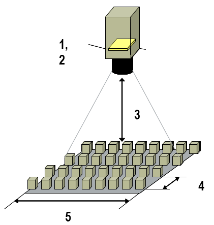
1.Sensor resolution: Camera sensor pixel size by number of columns and rows
2.Sensor size: Physical area of sensor array
3.Working distance: The distance from the front of the lens to the object under inspection
4.Feature Resolution: Smallest feature size on object that can be distinguished
5.Field of view: Area under inspection that the camera can acquire
The horizontal and vertical dimensions of the inspection area determine the Field Of View
Camera sensors contain an array of pixels
**Sense incident light intensity**Output video data through registers
Determining Necessary Sensor Resolution:
To be properly recognized by image processing algorithms, the smallest feature in the image must be represented by at least
two pixels
minimum sensor resolution = (FOV /
feature resolution) x 2
NOTE: If your required sensor resolution does not correspond to a standard sensor resolution, choose a camera whose sensor resolution is larger than that you require, or use multiple cameras.
Another important factor that
affects your camera choice is the physical size of the sensor, known as sensor size. The sensor’s diagonal length
specifies the size of the sensor’s active area. The number of pixels in your
sensor should be greater than or equal to the pixel resolution.
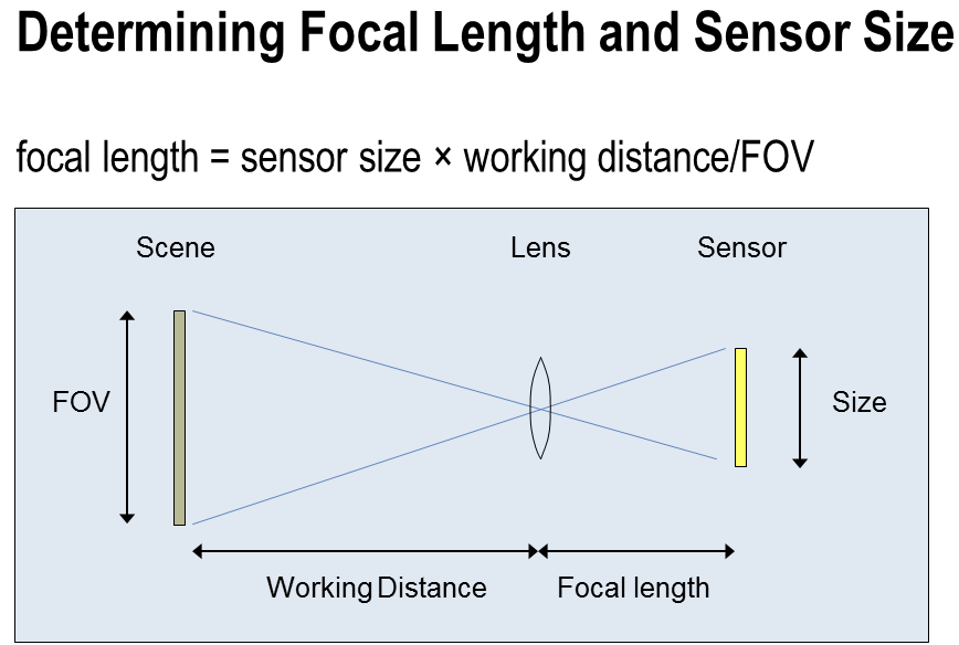
Lenses are manufactured with a
limited number of standard focal lengths.
Common lens focal lengths include 6 mm, 8 mm, 12.5 mm, 25 mm, and 50
mm. Once you choose a lens whose focal
length is closest to the focal length required by your imaging system, you need
to adjust the working distance to get the object under inspection in focus.
Lenses with short focal lengths
(less than 12 mm) produce images with a significant amount of distortion. If your application is sensitive to image
distortion, try to increase the working distance and use a lens with a higher
focal length. If you cannot change the working distance, you are somewhat
limited in choosing a lens.
 |
| Determining Focal Length & Sensor Size |
Image Scan Type & Their Difference
 |
| Image Scan Type & Their Difference |
Camera Format: Analog
Analog cameras output video signals
in an analog format. The horizontal sync
(HSYNC) pulse identifies the beginning of a line; several lines make up a
field. An additional pulse, the vertical
sync (VSYNC) identifies the beginning of a field. The reason the pulse was low was so that data
would not be output during reset of cathode.
In television broadcasting, the front
porch is a brief period (about 1.5 microsecond) inserted between the end of
each transmitted line of picture and the leading edge of the next line sync
pulse. Its purpose was to allow voltage levels to stabilize in older
televisions, preventing interference between picture lines.
Back porch refers to the portion in each
scan line of a video signal between the end (rising edge) of the horizontal
sync pulse and the start of active video. It was originally allocated to allow
the slow electronics in early televisions time to respond to the sync pulse and
prepare for the active line period. With
faster electronics making the delay unnecessary, the period
has found other uses, including color burst and sometimes embedded audio info.
Black
level - voltage below which everything is digitized to black.
White
level - voltage above which everything is digitized to white.
Color burst is a signal used to
keep the chrominance subcarrier synchronized in a color television signal. By
synchronizing an oscillator with the color burst at the beginning of each scan
line, a television receiver is able to restore the suppressed carrier of the
chrominance signals, and in turn decode the color information.Analog Cameras: Progressive Scan
Progressive scan cameras are
typically used in applications where the object or the background is in
motion. Instead of acquiring the image
one field at a time and then interlacing them for display, the CCD array in
progressive scan cameras acquires the entire scene at once. If you use a standard analog camera in a
motion application, there is a slight delay between the acquisition of each of
the two fields in a frame. This slight
delay causes blurring in the acquired image.
Progressive scan cameras eliminate this problem by acquiring the entire
frame at once, without interlacing. If
you have motion in a scene and you only have a standard analog camera with
interlaced video, you can use the National Instruments configuration software
to scan only one field of each frame, which will eliminate blurring in the
acquired image.
Camera Format: Digital
Digital cameras use three types of
signals – data lines, a pixel clock, and enable lines.
**Data lines – Parallel wires that
carry digital signals corresponding to pixel values
**Digital cameras typically represent
pixels with 8, 10, 12, or 14 bits
**Color digital cameras can represent
pixels with up to 24 bits
**Depending on your camera, you may
have as many as 24 data lines representing each pixel
**Pixel clock – A high-frequency
pulse train that determines when the data lines contain valid data.
**The pixel clock frequency
determines the rate that pixels are acquired
**Enable lines – Indicate when data
lines contain valid data
**The HSYNC signal, also known as the
Line Valid signal, is active while a row of pixels is acquired. The HSYNC goes inactive at the end of that
row
**The VSYNC signal, or Frame Valid
signal, is active during the acquisition of an entire frame.
Digital line scan cameras consist
of a single row of CCD elements and only require a HYSNC timing signal. Digital area scan cameras need both HSYNC and
VSYNC signals.
 |
| Camera Formats In A Nutshell-Analog & Digital |
Lighting: An Important Consideration
Lighting is one of the most important aspects in setting up image processing environment.
**Separates the feature you want to inspect from the background of the image
**Makes your image processing easier and faster
**Reduces glare, shadows, and effects caused by changes in weather or time of day
Various Lighting Techniques Are Available, some of them are:If objects in your image are covered by shadows or glare, it becomes much more difficult to examine the images effectively. Some objects reflect large amounts of light due to the nature of their external coating or their curvature. Poor lighting setups in the imaging environment can create shadows that fall across the image.Whenever possible, position your lighting setup and your imaged object such that glare and shadows are reduced or eliminated. If this is not possible, you may need to use special lighting filters or lenses, which are available from a variety of vendors.
**Ring Ligting
**Strobe Lighting
**Back Lighting
**Diffused Lighting
~Vibhutesh Kumar Singh
Student At VIT Vellore
